This is an old revision of the document!
In this article, we will help you create a custom DMD to use with Batocera. We are using ZeDMD as a basis as it's a cost-effective yet powerful solution, and now fully supported on Batocera 40+.
First, the final result


Step 1 : purchase the hardware
The shopping list:
- 2 DMD panels (don't forget to choose two of them) DMD Panels
- 1 ESP32 and its shield ESP32+shield
- 16 male/male 10cm jumpers Jumpers
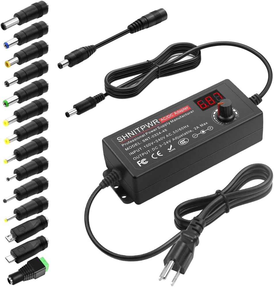
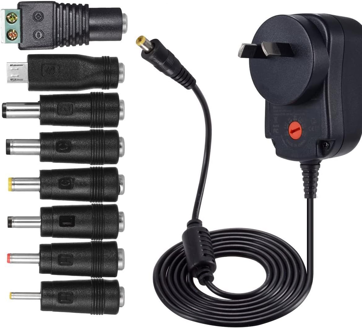
- 1 power supply Adjustable power supply or Switch-mode power supply - Note: the power supply may be optional if you build a 32×128 DMD (but is required for resolutions 256×64 and above).
- 1 plug Plug
You probably already have a plug at home.
Total cost including shipping: 39€ (on 2024 April 8).

Step 2 : Put the hardware together
Step 2.0 - external links
The original tutorials are not related to batocera.linux, but may be very useful to get some reference information.
The hardware part is the same for Batocera. However, the course of action for software configuration at the end is a little bit different.
Step 2.1 - Getting a power supply (for HD matrix)
Based on the display being used, some pixels may be too bright (causing glare and artifacts) or too dark (not visible), so it is useful to have a power supply with adjustable voltage. A power supply with universal terminals and an adjustable voltage is preferred, with the ability to use voltages near 5 volts at 2 amps. The more finely you can tune the voltage the better for adjustment.
It's also possible to get a static power supply voltage and then reduce its voltage by use of diodes (be careful of heat if only using a small amount of diodes): https://www.youtube.com/watch?v=x-p5LYgdEu4
Cut your own power wire
As an alternative to using a wall-wart power supply as pictured above, it is possible to splice a regular high-voltage power cable and connect that to a switch-mode power supply.
Incorrect wiring with power lines up to 240V can result in death by electrocution, exercise caution if choosing to go this route. If you have any concerns, use a universal power supply as specified above.


Step 2.2 - Plug LED matrices together with data and power wires
The data and power wires for the matrices are usually bundled with the matrices. Just plug them. Note that white arrows must go from left to right.


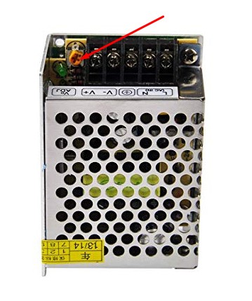
Step 2.2 - Plug the AC/DC power converter
Plug the 220V power on the AC (if you live in a 110V country, make sure you have the right AC/DC converter, and obviously the right plug). Be careful with the polarity of the wires, not all regions will use the same color-coding to indicate their polarity. Generally, the color code of AC wires are Phase (brown), Neutral (blue) and Ground (yellow/green).
Plug the 5V connector, and make sure you connect the correct polarity.
The orange screw on right of the AC/DC converter can be used to adjust the 5V voltage. It is necessary in case the image is not perfect, and the LEDs are “bleeding” a little bit. See the pictures below, in general, adjusting the screw to power down a bit the the voltage makes the image better.


Note: If you build a 32×128 DMD (not a “DMD HD” with a higher resolution), you can skip the power supply, and use the ESP32 microcontroller to power the LED matrices. It will draw current from the USB connection to the PC, and if the PC provides USB 2.0 or higher, i.e. most PC built in the past 20 years, it should be sufficient to power both the microcontroller and the LED panels connected to it.
To do so, you need to connect the red power wire from the LCD panel to the VIN pin on the ESP32 (5V) and the black wire to the GND pin (ground).
Step 2.3 - Microcontroller

Insert the ESP32 in its shield. This will be an easier way to plug the jumpers, as this will be a required part of the setup at a later stage.
Before plugging in the ESP32 board into the computer (ideally a computer running under batocera.linux), run the following command:
ls /dev/ttyUSB*
The result can be an error (no such file or directory) or a list of files (/dev/ttyUSB0 or /dev/ttyUSB0 /dev/ttyUSB1 or …)
Now, plug the ESP32 USB-C connecter to a USB port on that computer.
Run the ls command again the command, so that you can identify the device name the ESP32 microcontroller takes:
ls /dev/ttyUSB*
As a general rule, you would have gotten a no such file or directory error message before plugging in the ESP32, but now you should see a device name like /dev/ttyUSB0 once plugged in. This means that the ESP32 can now be identified as a Unix pseudo-file /dev/ttyUSB0.
In case you had a /dev/ttyUSB0 device before pluggin in, you would now get /dev/ttyUSB0 /dev/ttyUSB1 once the ESP32 is connected. This means that the ESP2 can now be identified as a Unix pseudo-file /dev/ttyUSB1.
Execute the following command, and don't forget to replace ttyUSB0 by ttyUSB1 if necessary, based on the previous explanation.
wget https://github.com/PPUC/ZeDMD/releases/download/v3.6.0/ZeDMD-128x32.zip
unzip ZeDMD-128x32.zip
wget https://github.com/espressif/esptool/releases/download/v4.7.0/esptool-v4.7.0-linux-amd64.zip
unzip esptool-v4.7.0-linux-amd64.zip
chmod a+x ./esptool-linux-amd64/esptool
./esptool-linux-amd64/esptool --port /dev/ttyUSB0 --chip esp32 write_flash 0x0 ./ZeDMD.bin
The first line downloads the ZeDMD firmware for a 128×32 matrix.
The second line unzips it.
The 3rd line downloads the tool we are going to use to flash the firmware on the ESP32 board.
The 4th line unzips that tool.
Th 5th line makes the tool executable.
The last line flashes the firmware on the ESP32 device conencted as /dev/ttyUSB0.

Step 2.4 - Plug the microcontroller
Check that your ESP32 is the 30-pin model (by counting the number of pins). There are several models, some with another number of pins, but this one seems to be the most common.
Now, you must plug the data wire to the ESP32 by respecting the pin codes as described in the following images.


There are 15 pins to plug in total.
The pin E can be omitted.
The pin called LAT is the pin STROBE.
Example : plug a pin in the data cable on G1. G1 pin corresponds to pin IO26. Thus on the ESP32 side, plug it in the IO26.

Note: if you don't use a dedicated power supply, plug the red wire from the LCD panel to the VIN pin of the ESP32 (+5V) and the black wire to the GRD pin (ground).
Step 2.5 - Final assembling

Step 2.5 - First boot
Plug your DMD the power wall socket. You should see the ZeDMD logo and the version.
The logo may be not perfect, as you can see on this picture, but no panic this is an easy fix: adjust the voltage to a slightly lower value to make it nicer (the orange screw on the power supply as explained at the beginning of this page).

Step 3 - Batocera.linux software configuration
Plug your DMD with the USB-C cable to the Batocera box.
Go in MAIN MENU → SYSTEM SETTINGS → SERVICES and start (or stop/start) the dmd_real service.
Get back to the main menu, and switch to a different system, or select a game in EmulationStation. The images, or the names of the games (in case you don't have the right images) should appear on your DMD.

Step 4 : finalize the DMD hardware
Make sure you steadily lock the LED matrices, and if you're handy enough, make a nice case to wrap things up.

Create a case as you can.
Issues
Lines issues
Check the pins. Some bad quality pins may create interference.


- hardware/diy_zedmd.1722317722.txt.gz
- Last modified: 22 months ago
- by atari